
Structural Mechanics and Infrastructure Materials Lab
The Structural Mechanics and Infrastructure Materials Laboratory (SMIML) is a facility for small-scale and full-scale structural testing, model testing, stress analysis, and material property determination of various materials, systems, composites, and structures.
A range of large to small-scale experiments on tension, flexural, compression, and fracture tests are conducted using closed-loop uniaxial and biaxial test systems. Analytical simulations, modeling, and experimental verifications are also conducted. These test machines which are rated from 5 to 4 MN (1-90 kips) in axial force capacity are operated using digital controller technology. Instrumentation for displacement and strain measurement with non-contact and Digital Image Correlation (DIC) in addition to multichannel data acquisition and data processing software is available. A strong floor is available for full-scale structural testing. The laboratory is also equipped with environmental chambers for testing specimens from 15ºF to 300ºF. Experiments such as fracture, creep, fatigue, and cyclic loading are being conducted on various materials and structures.
Available Testing Machines and Their Purpose
- State-of-the-art closed-loop high-performance digital servo-controlled MTS mechanical testing system with a capacity of 22,000 lbs. With an integral actuator, crossheads, and force transducers, this machine is used for tension, high cycle fatigue low cycle fatigue, creep, fatigue crack growth, and fracture toughness of materials ranging in strength from plastic to aluminum, composites, and steel. Mid-scale experiments using closed-loop controlled tension, flexural, compression, and fracture tests can be conducted.
- Similar to the MTS machine capabilities, a state-of-the-art closed-loop digital servo-controlled Instron mechanical testing system with a capacity of 55,000 lbs and SBEL uniaxial tension-compression mechanical test system with a capacity of 110,000 lbs is also available.
- Strain-gage excitation and amplification equipment in addition to a number of auxiliary measurement instruments (LVDT’s, signal conditioning devices, extensometers, etc). Also, microcomputer-based systems for general-purpose data acquisition, analysis, and data reduction are available.
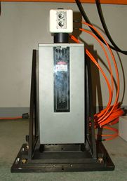
- Non-contact laser extensometer (LE). This equipment is utilized to measure the true displacement of the specimen during testing. The LE measures elongation due to loading by determining the displacements of two points on a specimen. The LE head unit consists of reflecting mirrors and lenses and optical detectors. Incoming laser beams are split and reflected to the surface of the specimen. The light is reflected off of the surface of the specimen and collected by the optical detectors, which relays this information to the control and display unit via the High-Speed Accessory. A picture of the Extensometer is shown below in Figure 1
- MTS high rate servo-hydraulic testing machine with a maximum speed of 14 m/s with a load capacity of 200 kN. This machine also operates with closed-loop for tensile and compression testing at rates lower than 0.25 m/s. The velocity of the stroke/actuator is controlled by a servo-valve. The more open the servo valve, the higher the velocity of the actuator.
- High-speed imaging applications using a Phantom v.7 high-speed digital camera is used to measure the visual displacement of a sample. This camera has a 2 GB onboard memory with sample rates of up to 15,000 fps (frame per second) with a resolution of 256 x 512 pixels. The pictures are stored in a computer via an integrated quick-release connector.
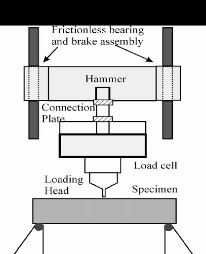
- Impact test set-up based on a free-fall drop of an instrumented hammer. The schematic of the system is presented in Fig. 2. The drop heights range from 1 to 200 cm and can be controlled by means of an electronic hoist and release mechanism. An anti-rebound system consisting of a pneumatic brake system triggered by a contact type switch is used to stop the hammer after the duration of the impact is completed. The experimental set-up consists of free weight, frictionless bearings along with the drop columns, load cell, connection plate, and a set of threaded rods. The hammer releases from a predetermined drop height by means of an electronic brake release mechanism.
A dynamic biaxial testing setup comprises of two actuators which are capable of applying displacement velocity and measuring the displacement of the test specimen in two orthogonal directions independently, two load cells with a capacity of 20 and 50 kips which are used for force measurement, a grip assembly to hold the specimen, a sliding block on a steel roller which is mounted on the ground, and connecting bars and universal joints, as shown in Figure 3. The load cell with a capacity of 20 kips is used to measure the force in a vertical direction, and the other was used to measure the force in the horizontal direction. The grip assembly can hold specimens with size up to 6×6 inches.
Large scale load frame setup with two 200 kips load-control hydraulic rams creating a total vertical load of 400 kips attached with adjustable reaction supports using a strong floor system suitable for flexure tests of large segments.
Large scale segment compression setup with two 200 kips load-control hydraulic rams creating a total vertical load of 400 kips suitable for thrust load tests and compression tests of large size concrete sections using strong floor systems. The lab is equipped with LVDTs, strain gauges, DIC and string sensors for measuring displacements. A picture of the string sensors is shown in figure 5.